The network layer is the third layer of the
OSImodel. It routes and forwards packets between networks, from end to end. Internetworking is built onIP, and the basic unit of transmission is theIPdatagram. This chapter covers the core protocols and techniques of the network layer.
The essence of internetworking is IP; transmission happens through IP datagrams.
1.1. IP
IP provides a connectionless, unreliable datagram service.
- Connectionless: The sender does not need to establish a connection with the receiver before sending data. Each datagram travels independently, so neither arrival order nor completeness is guaranteed.
- Unreliable:
IPhas no error recovery or retransmission mechanism. If a datagram is lost or corrupted in transit, theIPlayer itself does not handle it. Reliability is left to higher-layer protocols such asTCP.
1.1.1. IPv4 Datagram Format
An IP datagram consists of a Header and Data. The header is normally 20 bytes long and contains the key information needed for routing and forwarding.
- Version (4 bits): Identifies the
IPversion. ForIPv4, the value is 4. - IHL — Internet Header Length (4 bits): The length of the entire
IPheader, measured in 4-byte (32-bit) units. For example, a value of 5 means a header length of 5 * 4 = 20 bytes. The minimum is 5 (20 bytes), and the maximum is 15 (60 bytes). - ToS — Type of Service (8 bits): Specifies the datagram’s priority and quality-of-service (
QoS) requirements, such as minimum delay or maximum throughput. - Total Length (16 bits): The total length of the
IPdatagram, including both header and data, in bytes. The maximum is65535bytes. - Identification (16 bits): Uniquely identifies a datagram. When a datagram is too large and has to be fragmented, all its fragments share the same identification value so the receiver can reassemble them.
- Flags (3 bits):
- Bit 1: Reserved; must be 0.
- Bit 2:
DF (Don't Fragment). When set to 1, routers must not fragment the datagram. If it is too large to pass through, the router drops it and returns anICMPerror message. - Bit 3:
MF (More Fragments). A value of 1 means more fragments follow. A value of 0 means this is the last fragment, or the datagram was not fragmented.
- Fragment Offset (13 bits): The fragment’s position within the original datagram. The offset is measured in 8-byte units.
- TTL — Time to Live (8 bits): Sets the maximum number of hops, or routers, a datagram can pass through. Each router decreases
TTLby 1. WhenTTLreaches 0, the router drops the datagram and sends anICMPTime Exceeded message to the source host. This prevents datagrams from looping through the network forever. - Protocol (8 bits): Identifies the higher-layer protocol carried in the data portion of the
IPdatagram. For example,6meansTCP,17meansUDP, and 1 meansICMP. - Header Checksum (16 bits): Checks whether the
IPheader was corrupted in transit. It covers only the header, not the data. - Source IP Address (32 bits): The sending device’s
IPaddress. - Destination IP Address (32 bits): The receiving device’s
IPaddress. - Options (variable length): Used for special processing, such as recording the route or timestamps. Options are uncommon because they increase the header length and reduce processing efficiency. If options are present, the header length field is greater than 5.
1.1.2. IP Fragmentation
When an IP datagram exceeds a link’s Maximum Transmission Unit (MTU), a router needs to split it into smaller datagrams. This is called fragmentation.
- The Identification, Flags, and Fragment Offset fields work together so the destination host can reassemble the fragments correctly.
- All fragments share the same identification value.
- Every fragment except the last has its
MFflag set to 1. - The Fragment Offset field records the position of each fragment’s data within the original data.
1.2. ICMP
ICMP: Internet Control Message Protocol
Direction: host/router -> source (sender)
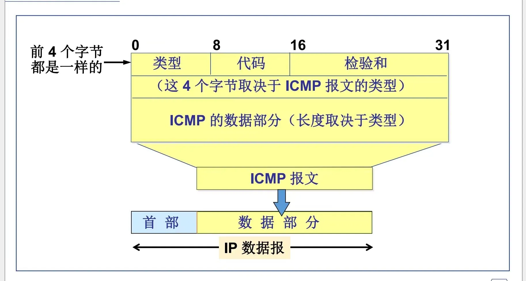
The Code field provides more detail. I won’t go into those details here. The code behind the code, I guess?
However, first I want to untangle these four bytes, what the diagram shows, and the difference between hexadecimal and binary.
The 0 8 16 31 positions in the diagram span 32 bits: 32 binary digits. The Type field is 1 byte, or two hexadecimal digits. In other words, when you read a datagram, you see two hexadecimal characters for this field. But diagrams love to show lengths in bits.
8 binary digits = 2 hexadecimal digits = 1 byte
| Type | ICMP Message Type |
|---|---|
| 0 | Echo Reply |
| 3 | Destination Unreachable |
| 4 | Source Quench |
| 5 | Redirect (change a route) |
| 8 | Echo Request |
| 9 | Router Advertisement |
| 10 | Router Solicitation |
| 11 | Time Exceeded for a Datagram |
| 12 | Parameter Problem on a Datagram |
| 13 | Timestamp Request |
| 14 | Timestamp Reply |
| 15 | Information Request (obsolete) |
| 16 | Information Reply (obsolete) |
| 17 | Address Mask Request |
| 18 | Address Mask Reply |
ICMP messages fall into two broad categories:
Error-reporting messages and informational messages (query messages).
-
Error-reporting messages
-
3Destination Unreachable -
4Source Quench -
5Redirect (change a route) -
11Time Exceeded for a Datagram -
12Parameter Problem on a Datagram
-
-
Informational messages (query messages)
-
0Echo Reply -
8Echo Request -
9Router Advertisement -
10Router Solicitation -
13Timestamp Request -
14Timestamp Reply -
17Address Mask Request -
18Address Mask Reply
-
The commonly used types are 3, 11, 0, and 8.
3 and 11 are error-reporting messages.
0 and 8 are informational messages.
1.2.1. Common ICMP Message Types
1.2.1.1. Destination Unreachable (3)
As the name suggests, Destination Unreachable means the destination cannot be reached. The Code field explains why.
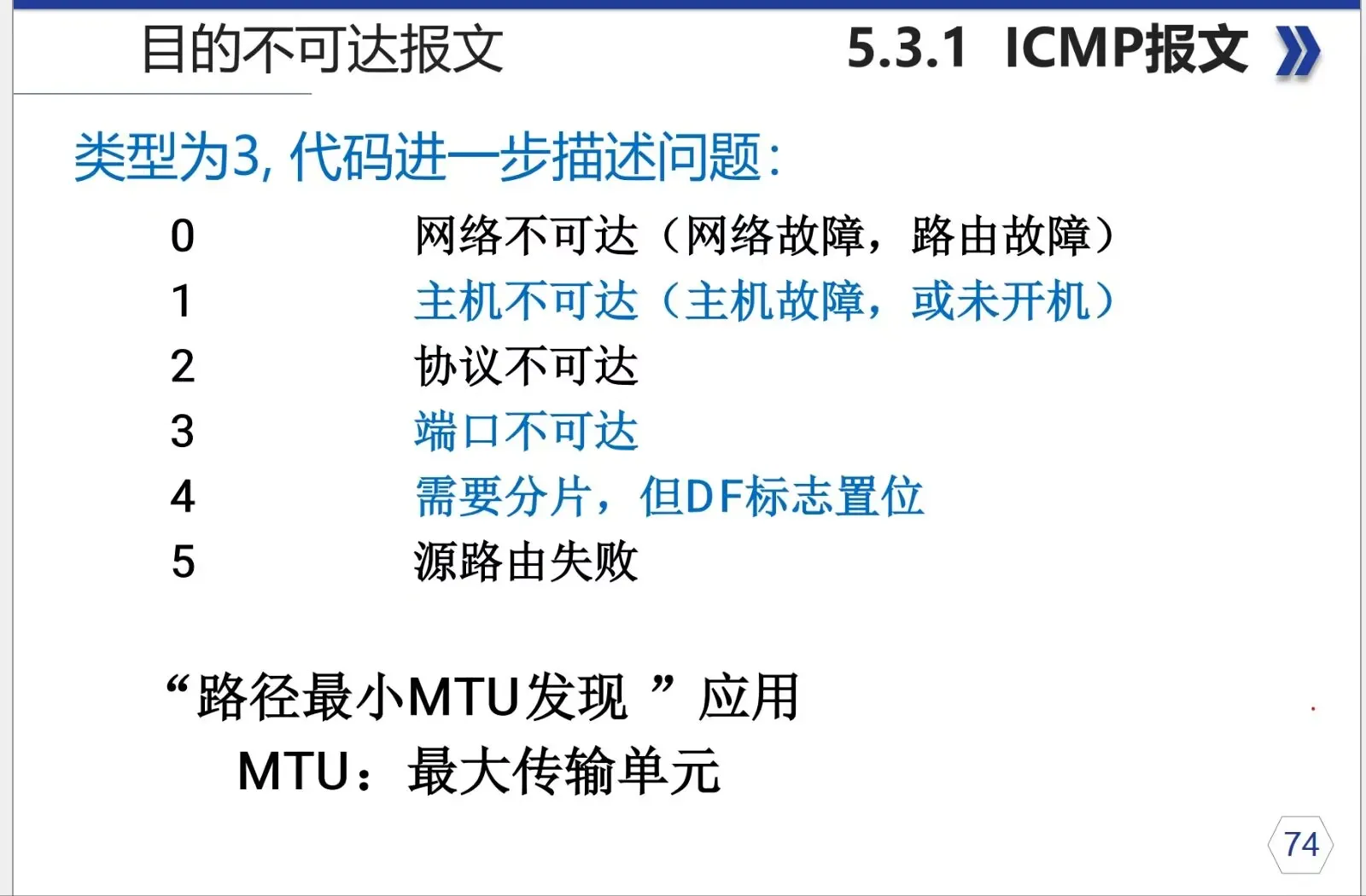
So the Code field contains hexadecimal values such as 00, 01, and so on.
MTUis the largest packet size that can be transmitted through a network interface.The
minimum MTU along a pathaffects transmission, especially when the path includes different network devices. If a device along the path cannot handle a packet that large, it drops or fragments it.An application using
Path MTU Discoverycan therefore determine theMTUand avoid fragmentation.
1.2.1.2. Time Exceeded (11)
The Code field identifies the kind of timeout:
00 — IP TTL (Time to Live) expired in transit.
01 — Fragment reassembly timed out.
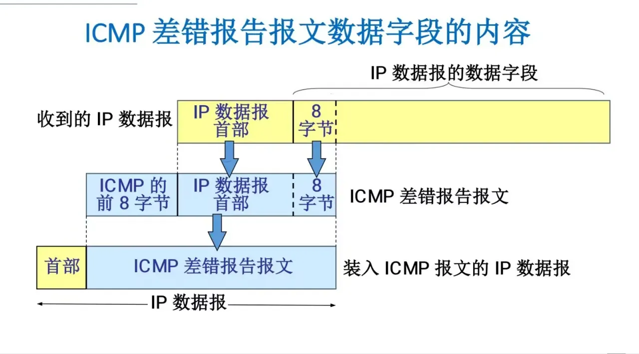
TTL expiration can be used to trace a route (
tracert).How route tracing works:
- The tool sends successive packets with increasing
TTLvalues to work its way along the path.- Each router decreases
TTLby 1. When it reaches 0, the router drops the packet and returns anICMPTime Exceeded message.- By collecting replies from intermediate routers, the tool can display the path and the latency at each hop.
1.2.1.3. Echo Request and Echo Reply (Types 8 and 0)
These are the messages used by the familiar ping command.
- PING (
Packet InterNet Groper): Tests connectivity between two hosts. - Host A sends an
ICMPEcho Request (type 8) to host B. - If host B receives it, it replies with an
ICMPEcho Reply (type 0). pingis a typical example of an application-layer program using network-layerICMPdirectly, bypassing transport-layerTCPorUDP.
1.3. ARP (Address Resolution Protocol)
On a local area network such as Ethernet, frames ultimately travel using MAC addresses (physical addresses), not IP addresses. So when a host such as 192.168.1.100 wants to communicate with another host on the same network, such as 192.168.1.50, how does it find the other host’s MAC address? That is what ARP does.
Definition: ARP (Address Resolution Protocol) resolves, or maps, a known IP address (a network-layer address) to its corresponding MAC address (a data-link-layer address).
How it works:
- Check the
ARPcache: Host A first checks itsARPcache table for aMACaddress corresponding to the destinationIPaddress,192.168.1.50. If it finds one, it uses thatMACaddress to build and send the frame. - Send an
ARPrequest: If no entry exists, host A broadcasts anARPrequest on the LAN. The message essentially says: “Who hasIPaddress 192.168.1.50? Please tell me yourMACaddress.” Because it is a broadcast, every device on the network receives it. - Unicast an
ARPreply: Every device on the network examines the request, but only host B, whoseIPaddress is192.168.1.50, replies. Host B sends anARPreply directly to host A by unicast: “MyIPaddress is192.168.1.50, and myMACaddress isXX:XX:XX:XX:XX:XX.” - Update the
ARPcache: After receiving the reply, host A knows host B’sMACaddress. It stores the mapping (IP -> MAC) in itsARPcache for later use and can then send data to host B.
The ARP cache: Each host maintains an ARP cache containing recently resolved IP-to-MAC mappings. Entries have a lifetime, usually a few minutes, and are removed when they expire to keep the information current.
1.4. DHCP (Dynamic Host Configuration Protocol)
When a new device, such as a laptop or phone, joins a network, it needs an IP address to communicate. Manually configuring every device’s IP address, subnet mask, default gateway, and DNS servers is tedious and error-prone. DHCP automates this process.
Definition: Dynamic Host Configuration Protocol (DHCP) is an application-layer protocol based on UDP. It lets a DHCP server automatically assign IP addresses and other network configuration parameters to clients.
The DORA process: The exchange is usually called DORA, after its four main steps.
Discover: The client, a newly connected device, broadcasts aDHCP Discovermessage to find an availableDHCPserver. Essentially: “I need anIPaddress. Is there aDHCPserver on this network?”Offer: EachDHCPserver that receives theDiscoverchooses an availableIPaddress from its pool and sends the client aDHCP Offer, by unicast or broadcast. Essentially: “Hello, I can give youIPaddress192.168.1.123, along with these other settings.”Request: The client may receive multiple offers. It chooses one, usually the first, and broadcasts aDHCP Requestto formally request thatIPaddress. Broadcasting tells all theDHCPservers, including those whose offers were not selected, which offer it chose. Essentially: “Everyone, I’ve decided to useIPaddress192.168.1.123from server X.”Acknowledge: The selectedDHCPserver sends aDHCP ACK, confirming the lease and specifying its duration. The client can now use the IP address to communicate on the network.
1.5. Routing Protocols
IP itself forwards datagrams, but it does not know how to choose the best path. Routers run routing protocols to learn the network topology and build routing tables, which let them make informed path-selection decisions. Routing protocols fall into two main categories:
1.5.1. Interior Gateway Protocols (IGP)
IGPs exchange routing information within an Autonomous System (AS). An AS may be the network of a company, a university, or an Internet Service Provider (ISP).
- RIP (
Routing Information Protocol)- Type: Distance-vector.
- How it works: RIP routers periodically exchange their entire routing tables with their neighbors. The metric is hop count: a route is better when it passes through fewer routers.
- Characteristics: Simple to implement, but with clear drawbacks: a maximum of 15 hops, slow convergence, and susceptibility to routing loops. It has largely been replaced by
OSPF.
- OSPF (
Open Shortest Path First)- Type: Link-state.
- How it works:
OSPFrouters exchange Link-State Advertisements (LSAs), rather than routing tables. Each router collects the network’sLSAsand builds a complete local map of the topology. It then uses Dijkstra’s algorithm to calculate the shortest path to each destination. - Characteristics: Fast convergence, no routing loops, support for Variable-Length Subnet Masks (
VLSM), and areas for better scalability. It is the most widely usedIGPin enterprise networks today.
1.5.2. Exterior Gateway Protocols (EGP)
EGPs exchange routing information between Autonomous Systems (ASes) and form the backbone of the Internet.
- BGP (
Border Gateway Protocol)- Definition: BGP is the only exterior gateway protocol currently in use. It does more than look for the shortest path: it is a path-vector protocol that can choose routes according to administrator-defined policies, including cost, security, and political considerations.
- Characteristics: Highly stable and scalable. It is the Internet’s core routing protocol, connecting thousands of Autonomous Systems around the world.
1.6. IPv6
With the rise of the Internet of Things and the rapid growth of the Internet, the IPv4 address space, about 4.3 billion addresses, has been exhausted. Its successor, IPv6, offers a vast address space and a range of improvements.
Main advantages:
- A huge address space:
IPv6uses 128-bit addresses, theoretically providing2^128addresses, enough for any imaginable demand over the next several centuries. - A simpler header: The
IPv6header has a fixed length of 40 bytes. It removes uncommon or redundantIPv4fields such asIHL, Identification, Flags, Fragment Offset, and Header Checksum, making packet processing more efficient for routers. - No router fragmentation:
IPv6requires the sending host to perform PathMTUDiscovery (PMTUD) before transmission so packets do not exceed the smallestMTUalong the path. Routers no longer fragment packets, greatly reducing their workload. - Enhanced security:
IPsecwas designed as a mandatory part ofIPv6, although it later became optional. It provides end-to-end encryption and authentication at the network layer, offering much greater security thanIPv4. - Stateless Address Autoconfiguration (
SLAAC): AnIPv6host can use the prefix advertised by a router, together with information such as its ownMACaddress, to generate a globally uniqueIPaddress and connect without aDHCPserver. - Improved Neighbor Discovery Protocol (
NDP):IPv6uses Neighbor Discovery Protocol (NDP), based onICMPv6, to replace functions such asIPv4’sARPandICMProuter discovery. It handles address resolution, router discovery, Duplicate Address Detection (DAD), and more, with greater efficiency and capability.
1.7. IGMP (Internet Group Management Protocol)
When data needs to reach a specific group of interested hosts, rather than one host (unicast) or every host (broadcast), multicast is used. IGMP manages membership in these multicast groups.
Definition: Internet Group Management Protocol (IGMP) lets hosts tell their local router that they want to join or leave a particular multicast group.
How it works:
- Joining a group: When an application on a host wants to receive data from a particular multicast group, such as a video stream, the host sends an
IGMPMembership Report to its local router. - Maintaining membership: The router periodically sends
IGMPQuery messages to ask whether any hosts on the local network are still interested in a multicast group. Members still in the group reply with reports. - Leaving a group: When a host no longer wants the data, it sends an
IGMPLeave Group message.
IGMP only handles communication between hosts and their local router. Routers use dedicated multicast routing protocols, such as PIM, to build distribution paths between themselves.
1.8. NAT (Network Address Translation)
NAT is a key technique designed to delay IPv4 address exhaustion. It allows many computers within an organization to use private IP addresses while sharing one or a small number of public IP addresses when communicating with the Internet.
Definition: Network Address Translation (NAT) runs on routers or firewalls and translates source/destination addresses and port numbers in IP datagrams between private and public networks.
Private IP address ranges (not routed on the public Internet):
10.0.0.0to10.255.255.255(Class A)172.16.0.0to172.31.255.255(Class B)192.168.0.0to192.168.255.255(Class C)
Types and how they work:
- Static NAT:
- Maps a private
IPaddress one-to-one to a public IP address. - Mainly used when an internal server, such as a web server, needs a stable address through which external networks can reach it.
- Maps a private
- Dynamic NAT:
- Maintains a pool of public
IPaddresses. When an internal host needs Internet access, an unused publicIPaddress is temporarily assigned to it from the pool. - When communication ends, the public
IPaddress is returned to the pool for another host to use.
- Maintains a pool of public
- PAT (
Port Address Translation) / NAPT:- This is the most common form of
NAT, also calledNAPT(Network Address and Port Translation). It maps multiple privateIPaddresses to different ports on one public IP address. - Process: Suppose internal host
192.168.1.100uses port50000to contact an external server. TheNATrouter changes the source address and port to a public IP and a new port, such as (202.100.1.1,60001), and records the mapping. When the external server replies to (202.100.1.1,60001), the router uses that record to restore the destination address and port to (192.168.1.100,50000) and forwards the packet to the internal host. - Advantage: Saves a huge number of public
IPaddresses. Hundreds or thousands of devices can access the Internet at once through a single publicIPaddress. - Disadvantage: Breaks the end-to-end connectivity model and can cause problems for some
P2Papplications orVoIPprotocols.
- This is the most common form of
1.9. IPsec (Internet Protocol Security)
IPsec is a suite of protocols that provides high-quality, interoperable, cryptography-based security for IP communication at the network layer. It offers data-origin authentication, data integrity, confidentiality through encryption, and protection against replay attacks. It is a core technology for building Virtual Private Networks (VPNs).
Two modes of operation:
- Transport mode:
- How it works: Encrypts or authenticates only the payload of an IP datagram. The original IP header remains unchanged; an
IPsecheader is inserted. - Use: Mainly for secure end-to-end communication between two hosts.
- How it works: Encrypts or authenticates only the payload of an IP datagram. The original IP header remains unchanged; an
- Tunnel mode:
- How it works: Encrypts and authenticates the entire original
IPdatagram, including its header and data, then encapsulates it in a new IP datagram. - Use: Mainly for secure gateway-to-gateway communication between two networks, such as a company’s headquarters and a branch office.
VPNgateways at the network edges handle it. This is the most common way to build aVPN.
- How it works: Encrypts and authenticates the entire original
Core protocols:
- AH (
Authentication Header): Provides data integrity and authentication, but no encryption. It ensures data has not been tampered with in transit, while the contents remain in plaintext. - ESP (
Encapsulating Security Payload): Provides data integrity, authentication, and confidentiality through encryption. It is the most widely used IPsec protocol.
1.10. VRRP (Virtual Router Redundancy Protocol)
If the router serving as a LAN’s default gateway fails, every host on that network loses access to external networks. This is a single point of failure. VRRP is a gateway redundancy protocol designed to address it.
Definition: Virtual Router Redundancy Protocol (VRRP) is a fault-tolerance protocol that groups several physical routers into a virtual router, providing a highly available default gateway.
How it works:
- Virtual router: Multiple physical routers in a
VRRPgroup share a virtualIPaddress and a virtualMACaddress. All clients on the network use this virtualIPaddress as their default gateway. MasterandBackup: At any given time, only one router in the group is theMaster. It owns the virtual IP address and forwards packets. The other routers areBackups.- Heartbeat detection: The
Masterperiodically sendsVRRPadvertisements, or heartbeats, to tell theBackuprouters that it is active. - Failover: If a
Backupstops receiving theMaster’s heartbeats for a certain period, it considers theMasterto have failed. The highest-priorityBackupbecomes the newMaster, takes over the virtualIPandMACaddresses, and starts forwarding traffic. - Seamless switchover: The transition is transparent to clients. They do not need to change anything, preserving network connectivity.
1.11. MPLS (Multiprotocol Label Switching)
MPLS is a high-performance, carrier-grade networking technology that operates between traditional IP routing (Layer 3) and data-link-layer switching (Layer 2). It is often called a Layer 2.5 technology.
Definition: Multiprotocol Label Switching (MPLS) assigns short, fixed-length labels to packets and forwards them based on those labels, rather than looking up a complex IP routing table at every hop.
How it works:
- Label distribution: Routers in an
MPLSnetwork, calledLSRs(Label Switching Routers), use protocols such asLDP(Label Distribution Protocol) to establish label mappings for IP prefixes, or routes. These mappings form the Label Forwarding Information Base (LFIB). - Ingress labeling (
Push): When an IP packet enters anMPLSnetwork, the ingress router (Ingress LER) performs a normalIProute lookup, then pushes one or moreMPLSlabels onto the packet. - Label switching (
Swap): Inside theMPLSnetwork, coreLSRsno longer inspect theIPheader. They read the outermost label, perform a fastLFIBlookup, swap it for a new label, and forward the packet to the nextLSR. - Egress label removal (
Pop): When the packet reaches the egress router (Egress LER), the label is removed, or popped. The originalIPpacket is restored and continues through standardIPforwarding.
Main advantages:
- Fast forwarding: Exact-match label switching is much faster than longest-prefix-match lookups based on
IPaddresses. - Traffic engineering:
MPLScan establish predetermined paths for traffic, calledLSPs(Label Switched Paths), rather than strictly following the shortest paths calculated by anIGP. This gives administrators fine-grained control over traffic to optimize bandwidth use or route around congestion. - VPN support:
MPLSis a foundation for large-scale, high-performanceVPNs, especiallyMPLS L3VPNs, and is widely used by majorISPsworldwide.
Still putting off the rest…